Ac Ac Converter Circuit Diagram
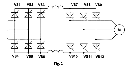
A solid-state AC-AC converter converts an AC waveform to another AC waveform. Fig 1: Classification of three-phase AC-AC converter circuits. This is a simple DC to AC Converter circuits,to converts 12VDC to 220VAC 50Hz/110V 60Hz as adjust frequency output using CD4047,MOSFET,power transistor and more. AC to AC Converter Working and Supplies. AC to AC converter circuit with a DC. Pls I need a detailed write up or schematic diagram for a cyclo converter using. Circuit Diagram. The following are the steps to convert 230V AC to 12V DC. Here's an instructable which helps you==>AC to DC converter.
This AC to DC converter circuit is capable of converting an alternative voltage within 70V – 260V range into a DC voltage within 180V to 350V DC range, so it can be used for 110V and 220V too. To achieve this voltage conversion we use a MC34161 rectifier as a voltage doubler at low input voltages and as a classic rectifier at high input voltages. Related Products: Input AC voltage/Output DC voltage table AC to DC converter circuit diagram MC34161 includes a reference power supply which delivers 2.54V at pin 1. The signal level applied at pin 2 is internally compared with a 1.27V voltage.

D5 zener diode, togheter with R1 and C4 provide IC’s required 12V voltage. Capacitor’s voltage of C2 and C3 must be greater than 250V. Bt169d Datasheet Pdf here. Attention: this ac to dc converter contains very high voltages that are deadly and you must be very careful!